
Chet.ie
Electonics, Projects and Ramblings – Make it, break it, hack it, mend it.
December 24, 2012 — 22:27
My brother has a solar panel on the roof of his house which is used to charge a 12v battery which runs the equipment in his attic, the routers etc. There is a proper solar regulator/battery charger which keeps the battery topped up. The problem is that when the sun isn’t shining (which happens a lot here!) the battery drains and eventually the voltage drops. He had bought a switch mode power supply that would take over from the solar regulator but he wasn’t sure how to wire it up to work as he wanted, which was to have the power supply on only when it was need so there would be no power wasted.
This is what i came up with for him.
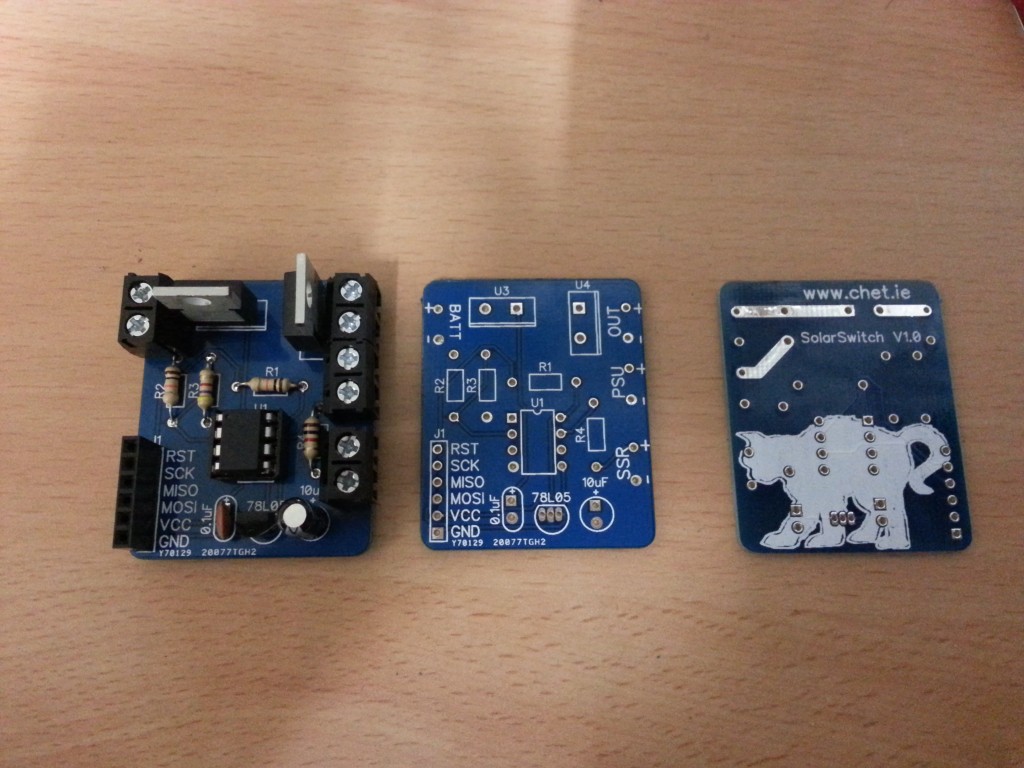
At the heart of it ia an ATmel attiny85, this measures the output of the battery through a voltage divider (to keep the attiny input voltage below 5v) If it drops below a certain value, say 11.5v, it will turn on a solid state relay which controls the mains feed to the 12v power supply. Once the battery voltage reaches an acceptable level the relay is switched off and the external devices continue to be powered from the battery. The battery and power supply are isolated from one another using two diodes to prevent current from flowing backwards into the power source not being used. I used MUR1560 diodes with a voltage drop of 0.4v as they are what i had to hand. While this means the output is 0.4v lower than we need both the power supply and battery charger can be adjusted to a higher voltage so the final output will be as required. Also onboard is a 7805 voltage regulator which powers the attiny85.
The attiny is running the arduino bootloader and the code is posted below.
[code]
int onVoltage = 11500; //define min allowed voltage (mV) – switch psu on
int offVoltage = 11800; //define voltage to turn psu off (mV)
int timeDelay = 5000; //define delay between checks (ms)
int rangeTop = 15681; //measured input when voltage divider voltage is 5000mV
int voltageinPin = 3; //attiny85 pin 2, connected to voltage divider
int relayPin = 2; //attiny85 pin 5, connected to relay
int voltagein = 0; //initialise variable to hold read voltage
void setup()
{
pinMode(relayPin, OUTPUT);
}
void loop()
{
voltagein = map(analogRead(voltageinPin),0, 1023, 0, rangeTop); //map pin value from 0 to max voltage
if(voltagein <= onVoltage){
digitalWrite(relayPin, HIGH); //turn relay on
}
else if(voltagein > offVoltage){
digitalWrite(relayPin, LOW); //turn relay off
}
delay(timeDelay);
}
[/code]
Due to the tolerances of the resistors it is best to measure the input voltage and adjusting it until the voltage divider gives an output of 5v. You can set your voltage divider to give yourself a large margin here, for mine the largest input voltage we can take is over 15v, this keeps the actual pin input voltage well below the 5v maximum. While you might loose some precision here its not needed anyway.
Power comsumption was 20mW, half of which was from the voltage divider and then there is also wasted energy in the diodes so there is room to improve if needs be, in this case it was perfectly adequate!
Comments:


It was either made by itead or seeedstudio, i can’t remember which now! I believe both use the same fab house anyway
January 7, 2013 — 19:32
Hi, i’m interested in your board. can you send me a copy of the schematic. I’m thinking of using it on my project 🙂
June 6, 2013 — 13:40
Nice little board!
I suppose the design was done by you. But where was it manufactured and assembled?