As you may have seen from the RC car mods posts, i had to add a voltage boost module in to get it working. While it worked perfectly for that purpose i was skeptical of the claimed specifications – as you should be when buying cheap stuff from ebay.
Here is the details from the ebay auction:
-
Input voltage: DC 3-4.4V
-
Output voltage: DC 5.5V
-
Output current: 700mA (max)
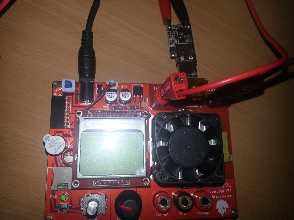
To test the module i used my iTead OverLoad dummy load. This allows you to set a current and it will vary the load to maintain the current passing into it.
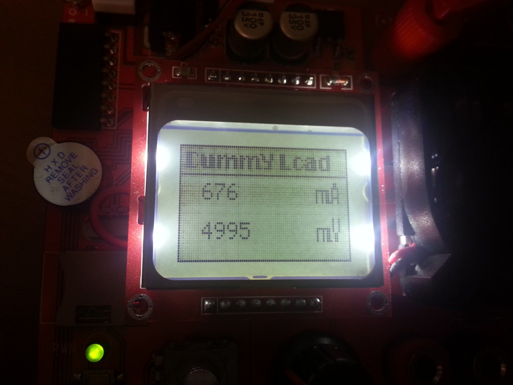
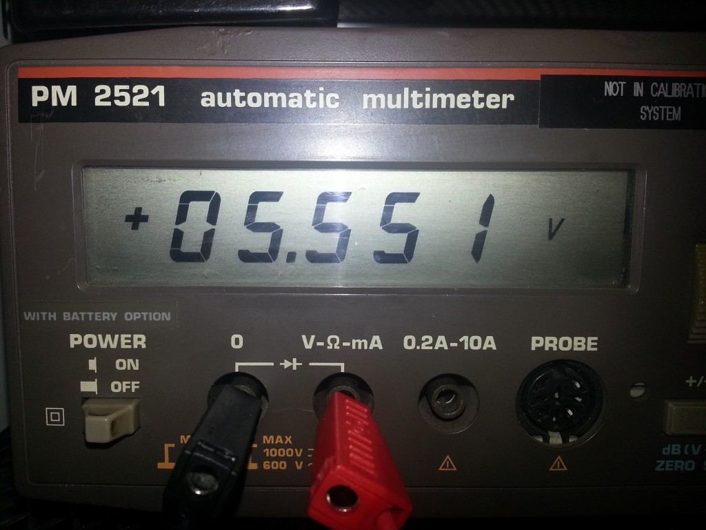
Here is the setup below. The OverLoad is powered from my Atten power supply(crocodile clips) with the output taken direct at the USB connector output. The output voltage is measured by my Philips PM2521 bench multimeter using the banana plug leads in the pic.
There was 3 things i wanted to test.
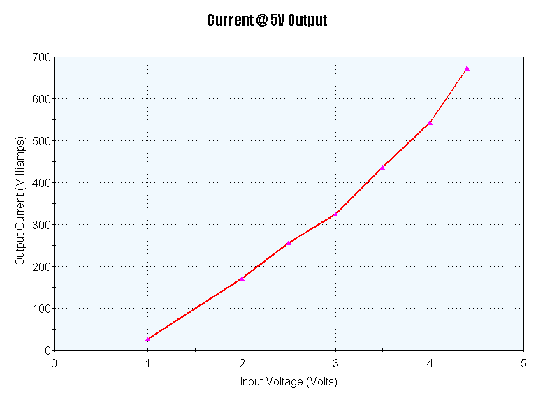
- How much current we could get with an outputof 5V
- How high of a voltage we can get out at the max rated 700mA
- The efficiency
Firstly, with no load the output voltage measured 5.5V at the max input of 4.4V. I lowered the input voltage all the way down and even at 0.2V it still showed 5.4V at the output. Only at 0.1V did it drop to 4.1V. Interesting but a bit useless with no load on it!
To measure the current with an output of 5V it was a case of setting the input voltage and adjusting the load until we had an output of 5V for all input voltages. Did we manage to get 700mA? No, but we got close. At 4.4V input we managed 670mA at 5V. At the other end of the scale with an input of 1v we managed 30mA at 5V.
The data is plotted below.
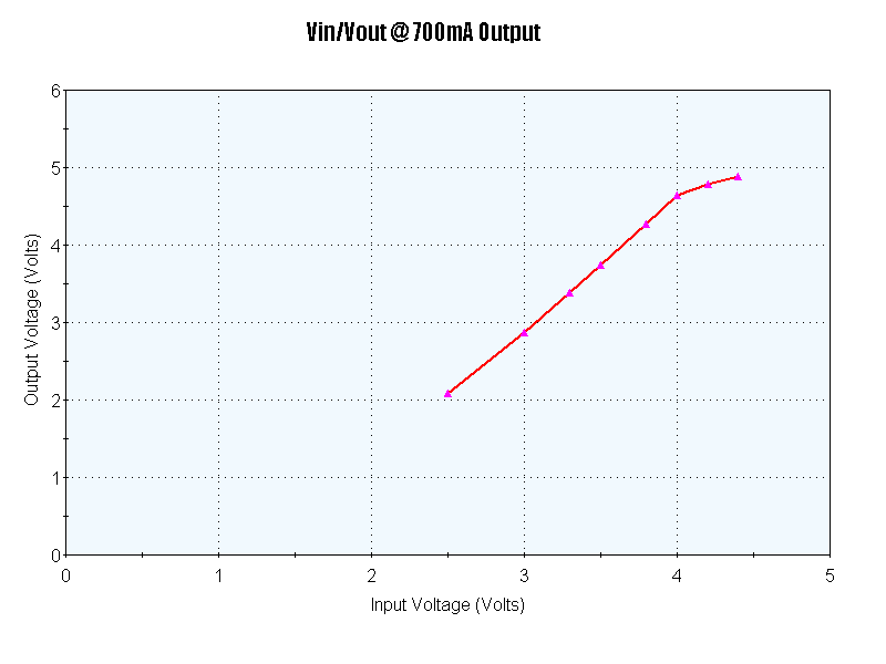
Now i wanted to see what voltage output could be got while maintaining 700mA output. This was simply a case of setting the OverLoad to 700mA and dropping the input voltage while recording the output voltage. For the 4.4V input there was an output of 4.89 volts which is within USB specs of 5V+/- 0.25V. However once we reach an input below 4.2V we fail below USB specs. I didn’t bother going below 2.5V input which gave an output of 2.1V.
Again, the data is plotted below.
The efficiency is calculated as Pout/Pin where Pin is the input power = input voltage x input current and Pout is output power = output voltage x output current.
The max efficiency was when the input voltage was highest which gave us a 84% efficiency rate, the lowest seen was 64%
Overall then its not a bad little module provided you’re not chasing high currents from it. One thing i didn’t check at the time was how noisey the output was, i will have to do that in the future.

Leave a Reply